Read capacitive humidity sensors with two digital IO lines
Reduce costs and parts count
© Joe Ellsworth 2009 - Free use for everyone, no warranty, keep my name in future versions
I also offer design and prototype services 206-601-2985
Read a capacitive humidity sensor without a ADC and only two additional components
Overview
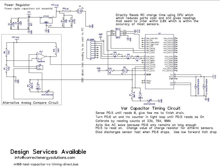
This document describes how to read a capacitive humidity sensor directly from a micro controller using 1 resistor, 1 diode the sensor and two IO lines. It does this without an ADC by measuring the amount of time it requires to charge the capacitor through a resistor until the charge level is sufficient to register as logic 1. As the humidity changes the capacitance changes which changes the time required to charge the circuit. We measure the time in a tight processor loop and average the readings to reduce hysteresis. The readings are calibrated to two known humidity points using aqueous salt solutions. The calibration allows simple conversion to percentages which can then be used internally or shipped out through a digital network such as RS422. Most humidity sensors change consistently at a given capacitance change per 1% humidity change so the humidity can be calculated as a direct correlation to capacitance changes.
While this circuit was designed specifically to support humidity sensors it should work the same with any circuit which uses a variable capacitor that predictably changes across it’s set of input such as stress gauges. It can be extended with lookup tables to support devices which do not deliver a linear ramp across it’s operating range.
Motivation
I ran out of ADC pins and didn't want to install a multiplexer or external ADC for my 3 humidity sensors. I was tired of paying $15 to $35 each for humidity sensors like the vout HM1500 or the digital Sensirion SHT75. In addition I found that many of the vout and freq out units had drifts exceeding 10% after 1 year in our application. My other issue is that the more sophisticated vout sensors keep getting model changes which requires design changes for us while the base level cap sensors remained the same and reliable. I needed an adequate solution that was cheaper and could be easily field re-calibrated. I looked at many of the 555 circuits but they seemed complex with lots of components which could have thermal drift. I wanted something that would be easy to integrate into remote mounted circuits dozens to hundreds of feet away while keeping costs low.
My design is based on reading the capacitance variance directly from the micro controller and have been reasonably satisfied with the results. The cheap sensors like the HCH-1000-002 and the HS1101 do not come pre-calibrated and I found over a 10% variance from sensor to sensor so calibration must be built into the software. Due to high rates of drift I needed a easy way to re-calibrate in the field.
Results
After a very primitive calibration run, I ran a quick check using a sodium chloride (table salt) calibration solution my readings after averaging ran +- 1.5% of the 75.3% expected which is within the hysteresis ratings of the HCH-1000-002 sensor. Improved algorithms with more sophisticated averaging would make this more accurate.
Basic Circuit Operation
The circuit is descried at http://correctenergysolutions.com/electronics/cap-humidity-sensor-circuit and is free to use. It basically uses a two digital IO lines one as a charge and the other as a sense. We charge the capacitor circuit through a resistor with a diode for fast drain back. We feed the sense line from the cap back to the micro controller. The capacitor is fully drained before the feed line is activated. We measure the time it requires for sense to convert from a logic low to logic high in a tight loop with a counter. Once the transition high on sense occurs the feed line is set to low which re-drains the sensor cap. As the capacitor value rises or falls with humidity the count value rises and falls proportionately. We measure the count in a tight loop because we found the variables in interrupt service for the timer caused undesirable variability in the readings.
Algorithm
· Sense PD.5 until reads off. Give few extra ms to finish drain.
· Turn on pd.6 and increment counter in tight loop until pd.5 reads as on.
· Average last reading into last 7 (N). Calculate the slope of change as far as count increments per percentage of humidity then convert then this into actual percentage change and add it to the low calibration point or subtract from low calibration point if below.
· Calibrate by reading counts at 33% and 100% RH.
· The circuit acts like an AC wave because PD.6 only remains on long enough for PD.5 to read as on then PD.6 drops which drains the capacitor.
· Change the value of charge resistor may be needed for different sensors.
· Diode discharges sensor fast when PD.6 drops. Use low forward voltage drop diode to minimize residual charge that must drop through the resistor.
Consistent transition detection
We found a good count value with reasonable resolution using a 20 Meg feed capacitor on the HCH-1000-002 and a 40 Meg for the HS1101. One concern was that the transition from logic low to logic high is defined as a range so I thought it would be sloppy. I checked this with no cap in circuit and by using a fixed capacitor. When the variable cap is removed from the circuit it consistently takes 18 cycles to charge the circuit whereas when the cap is present it ranges from 1080 to 1300. When we place a fixed capacitor in circuit it stays the same within a 6 or so cycles and normally stays within 1 cycle from test to test. I interpret this as a consistent transition voltage from low to high on sense which is basically doing the same thing as a analog comparator.
A analog comparator would probably be more accurate but I actually saw comparable variability up/down 1.5 to 3% when reading the vout HM1500 sensors through the ADC and had to run an averaging algorithm anyway. The difference is a sensor which is 4 times cheaper.
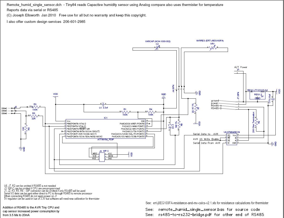
Remote Sensor with RS485 data feed good for 4,000 foot
This design is second generation, Instead of strict logic transition it uses a voltage divider to provide a reference voltage and then uses on CPU analog comparator sense charge rate.
· It uses the ACI (Analog Comparator) interrupt and the AVR 16 bit timer / counter to accumulate the time for the RC constant. The speed of the 20 Mhtz CPU combined with the speed of the counter and higher threshold value allowed the resistance on the feed resistor R7 to be reduced from 20 Meg to 1 Meg and still deliver higher resolution with faster reads
· It uses a high precision thermistor VR1 as the ground leg of a voltage divider to sense temperature as measured through the ADC.
· This circuit provides output via RS485 or a TTL serial that is compatible with most laptops. When using the RS485 circuit you must disconnect the normal power J1 as the power is fed in over the RS485 connector J2. The PC compatible serial output is on J2. It does not conform to RS232 specs but it has worked on every laptop I have used.
· The software includes EPROM storage of calibration data for the capacitive sensor C2. This allows field calibration using standard salt solutions.
Diptrace schematic PDF Schematic Source Code RS485 to RS232 Bridge
· When using the RS232 connector ensure that you connect the ground to the power connectors J2 before applying power in. Otherwise the circuit will operate through the ground connection to the serial port. This is not a problem when the circuit draws very little power but is very bad practice because a high current short could burn out traces on the laptop or PC mother board. Where this is a risk a 30Ma fuse should be added on the RS232 ground leg to avoid expensive damage to your development computer.
· On surprising result from this circuit is that the analog comparator result does not seem to be any more stable than the polling for change in logic levels from original Mega32 circuit. This indicates the transition from logic 0 to logic 1 on the AVR CPU is consistently applied at the same transition voltage even though the TTL spec provides range.
Basic Sensor Detection Source code
· Full Source code Interrupts on Analog comparator
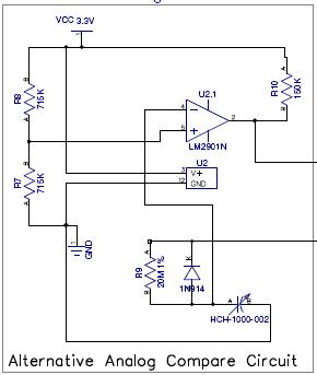 Alternative
circuit with Analog compare
Alternative
circuit with Analog compare
The analog compare circuit allows us to have a defined transition for transition from off state to on state. The voltage divider with R7 and R8 gives us a reference voltage of about 3.03 in a 5V circuit. As the variable capacitor charges it eventually obtains a voltage higher than reference which causes the output of the analog comparator to go low.
· The benefits of this approach are that it may allow use in CPU which do not provide consistent detection otherwise.
· Most AVR Mega CPU include a multiplexed analog compare that can provide the same functionality as the LM2901. The disadvantage of this approach is that it uses ADC pins and we seem to always be short of ADC pins so it was deemed more favorable to use a external analog compare chip and preserve the ADC lines.
· This circuit can allow the comparator and R9 to be moved to the end of the sensor cable and eliminate the long cable capacitance problems. In addition the single channel comparator such as the LM111 can provide enough current to directly drive a LTV-816 opto isolator on the main board which feeds output to the CPU line. This combination allows a very high resistance noise and spurious state changes while adding less than $1.00 per sensor to the costs. Once the LM111 and LTV-816 are combined at the end of the wire with the sensor the length of the sensor wire is limited only by the ability to drive the voltage out and back from the sensor. Both the LTV-816 and the LM111 can tolerate +- 30V swings so the circuit can be driven from RS232 levels to increase cable length. The disadvantage with this approach is that it would require 4 wires to the remote sensor. +Vcc, GND, Drive and Signal.
If going that far it makes sense to just mount a Tiny85 remotely with the sensor with a RS485 driver and use the normal circuit. By using the Tiny85 the thermister temperature sensor can also be used with both the temperature and humidity data transferred back over the RS485 bus. The cost would be closer to $5.00 for the CPU versus $1.00 for the analog comparator and opto coupler but cost difference seems worth while since 2 additional conductors will cost more than that for cables of any significant length.
· Because the cap voltage must reach the compare voltage to change the IO state on output it should take longer to charge or allow smaller charge resistor in R9. To date have not found that to be true.
· With a 30M resistor in R9 it’s count values are very similar to those returned from the simple circuit.
· This circuit uses inverse output from the direct drive to PD6 shown in the main circuit. As a result we must reverse the detection logic in the software.
· The voltage divider R7,R8 can be reused for multiple sensors.
· The analog compare chip and the feed resistor R9 could be remotely placed which would improve noise resistance.
· The 4 channel LM2901 costs $0.30 in qty 100 which only adds $0.075 cost per sensor.
· Single channel devices such as the LM111 should work the same way but where not tested.
Notes:
· My second circuit used a 8 Megahertz AVR CPU while my initial test was a 10 Megahertz CPU. I had to increase the resistance for the HCH-1000 sensors to 30 Meg when using polling to obtain sufficient resolution. My guess is that a faster CPU will allow correspondingly lower resistance while maintaining fidelity of measurement.
·
Calibration
· WARNING: Constant temperature is critical for calibration. Take the time to build our sample heat controller to keep solutions at constant temperature.
· Obtain at least two salt solutions one for low humidity and one for high humidity.
· Place sensor in sealed container in air above solution.
o Precise temperature control is critical. Even a 0.5C shift in temperature from beginning to end of the calibration run can result in a 3% difference in reported readings. I have another circuit for a precision TEC based temperature controller but a well insulated ice chest where you have placed a quart or gallon of water which is exactly at 20.1C will work. The extra .1 is used to heat the glass jars.
§ The sensor calibration numbers in the data statement are for 20C. Your calibration must be done at exactly 20C or the salts will give incorrect readings.
§ I have seen a 2C change in temperature take over 2 hours to stabilize the humidity in the salt chamber so minimizing temperature deviation during the test is critical.
§ Calibrate from the lowest humidity solution moving to the next higher in succession until the highest level humidity has been reached. It seems to cause overstatement of readings from the sensors when working downward.
§ Allow a minimum of 3 hours stabilization after the sensors have been inserted. 8 hours is better. Use the same amount of time for each calibration even if it does not appear to need it. Do not allow a longer soak in some of the chambers or it will distort the readings. The exception to this is if over 10 hours soak is used in each chamber then it may not matter.
o Well insulated glass container well is preferred.
§ We use a glass canning jar with hole drilled in lid.
§ There is about 2” of damp salt solution in bottom of jar. Do not add too much distilled water or the solution will not present accurately. I used about 0.5” salt with just enough water added to the salt that it is damp but not fully saturated.
§ We insert the sensors through the hold in lid and cover with duct tape to make air tight.
§ Wrap the entire jar with insulation to keep temperature constant.
§ When finished with the test replace lids with holes with liquid tight lids for storage.
§ Make sure sensor does not touch solution or it can be ruined.
o Leave for 3 hours at constant temperature and record reading in count level.
o I have found that calibration is time consuming because you end up waiting for the 3 hour stabilization curve for each solution. What I also found is that temperature changes across the 3 hour period cause accuracy problems in the calibration. I finally retrofit an old Ice chest with a TEC heating module and a temperature sensors to keep a bottle of water at exactly 20.1C. This bottle radiates heat into the rest of the ice chest and keeps things quite stable. See the thermister temperature measurement circuit and low side motor switch. I used the TEC as a heating element rather than a heat pump because ambient was well below my 20C set point and it took less time if I didn’t have to install the through the wall unit.
o Record the percentage and readings in the hi_r, hi_p,lo_r, lo_p constants basic source code.
· Recommend calibration at 33% and 76% but any two places in range are probably adequate.
· Best to build this into the software and store calibration in Non volatile memory to allow recalibration in field without re-programming.
· Notes:
o Found resistance on charge line to meet needs of the variable capacitor by experiment.
o If clock interrupts are used it will modify the calibration and will require re-calibration.
o Changing length of connection wire also adds capacitance and will require re-calibration. It is best to keep connection wire as short as possible and twisted pair.
o Human bodies and tanks of water can modify capacitance in wires running near them and may require re-calibration. For this reason it is best to build the micro controller into the sensor and send the data back via a digital network such as RS422 which is more immune to electrical interference.
o Resistors also change in value with temperature. To get most accuracy needs to all calibration point which takes temperature into consideration.
· Settings at 20C - Use these because they are closest to shirtsleeve room temp
o Regenerated Silica Gel = 0%
o Lithium Chloride = 11.31% +- 0.31%
o Potassium Acetate = 23.4% +- 0.32%
o Magnesium Chloride = 33.3% +- 0.21%
o Potassium Carbonate = 43.16 +- 0.33
o Magnesium Nitrate = 54.38 +- 0.23
o Sodium Chloride = 75.47 +- 0.14
o Potassium Chloride = 85.11 +- 0.29
o Potassium Nitrate = 94.62 +- 0.66
o Potassium Sulfate = 97.59 +- 0.53
o Distilled Water = 100
· Common salts as measured at 25C. Most sensors not reliable above 95% so calibration at 93% would be better than 100%.
o Silica Gel – 0%
o Lithium Bromide = 06.37%
o Lithium Chloride = 11.3%
o Potassium Acetate = 22.51%
o Magnesium Chloride = 32.78%
o Potassium Carbonate = 43.16%
o Magnesium Nitrate = 52.89%
o Sodium Bromide = 57.57%
o Potassium Iodide = 68.86%
o Sodium Chloride = 75.3%
o Potassium Chloride = 84.34%
o Potassium Nitrate = 93.5%
o Potassium Sulfate = 97.3%
o Distilled water = 100%
· Reference Material using salts for calibration
Some of these are hazardous, Use care when handling. We like magnesium Chloride, Sodium Chloride and distilled water because they are relatively safe to handle compared to Lithium Chloride which is more hazardous.
o http://www.smartec.nl/pdf/apphs1002.pdf - easy to understand list
o http://nvl.nist.gov/pub/nistpubs/jres/081/1/V81.N01.A06.pdf - The Definitive source most other articles reference - comprehensive list “humidity fixed points of binary saturated aqueous solutions” Lewis Greenspan, 'Humidity fixed points of binary saturated aqueous solutions', J. of Research, National Bureau of Standards, 81A (1977) pp 89-96
o http://www.absoluteastronomy.com/topics/Critical_relative_humidity - Critical humidity explained lists more chemicals but does not includes temperature correlation.
o http://en.wikipedia.org/wiki/Critical_relative_humidity - Wikpedia explanation of critical humidity.
o http://www.nkhome.com/pdfs/k3_k35_k4_calkit_web.pdf - calibration chart for a NK meter. Published at 25C, Lithium Bromide=6.37C Lithium Chloride=11.3%, Potassium Acetate=22.51%, Magnesium Chloride 32.8%, Potassium Carbonate=43.16%, Magnesium Nitrate=52.8%, Sodium Bromide=57.57%, Potassium Iodine=68.86%, Sodium Chloride=75.3%, Potassium Chloride=84.34%, Potassium Sulfate=97.3%
o http://www.natmus.dk/cons/tp/satslt/satsalt.htm the Relative humidity above saturated salt solutions at various temperatures – good chart with saturations at 5,10,15,20,25F easy to understand but not comprehensive list of chemicals. Instructions for mixing the chemicals.
o http://www.omega.com/temperature/z/pdf/z103.pdf - Equilibrium Relative Humidity Saturated Salt Solutions – included comprehensive list of temperatures for lithium chloride, potassium Acetate, Magnesium Chloride. - I like this chart the best.
o http://cool.conservation-us.org/waac/wn/wn13/wn13-1/wn13-106.html Controlling Relative Humidity with Saturated Calcium Nitrate Solutions
· Chemical Sources
Please make sure you read about and understand the hazards of dealing with these chemicals. Some are relatively safe like Sodium Chloride. Others can kill, main or blind you really fast. If I have a choice, I always choose the safest chemicals available. Ideally those FDA approved as food additives.
o http://www.highqualitychems.com/servlet/StoreFront?gclid=CKHh5tvCmJ8CFSgVagodb1L1_g
o