Hi-Side Switch 17 amps under $2.00
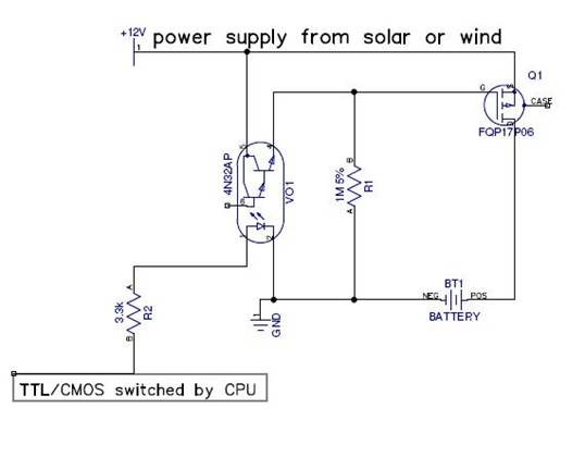
CPU driven hi-side switch using P-Channel Mosfet
© Joe Ellsworth 2009 - Free use for everyone, no warranty, keep my name in future versions
I also offer design and prototype services 206-601-2985
PDF Schematic Diptrace schematic Diptrace PCB Layout
Switch for Solar Charger supports PWM and battery charge limiting controlled from CPU.
Overview
This circuit was designed as part of a solar battery charger. It acts like a normally closed relay until the CPU drives the IO pin HI which disconnects the battery supply from power source. These could be easily combined to redirect the load to a different destination when the battery does not need the power. The same circuit can be used to control motors.
It’s primary feature is to allow charging of a battery even when battery and source supply is too low to run the CPU. It does this inexpensively with all digital components and allows the CPU to control PWM charging to limit charge rates and eliminate over charge.
It draws no extra power when in normal operation but does incur a 0.07V drop across Q1 when operating at 12V and 600mA draw. When the CPU activates VO1 to turn off Mosfet Q1 the current draw from the CPU to through R2 to drive the LED in VO1 is 5mA at the CPU operating voltage 5V or 3V. The power feed through R1 is 0.01mA.
Assumes common ground between battery and power supply.
I buy the PNP 17 amp transistors FQP17P06 at Qty 100 for $0.594, The 4N33M photo coupler Qty 100 is $0.33 The two resistors are $0.04 The 1M resistor R2 RNF 1/8 T1 1M 1% R is $0.0438 qty 100 the R2 resistor is about the same $0.0438. This brings our incremental switching cost to $1.04 addition to an existing board. Surface mount parts are available cheaper. These prices are from Digikey’s public web prices as of Jan 2010.
The Heat sink 513102B02500G costs $0.807 qty 100 and is rated to dissipate 8W at 80C. It should work pretty well until the power switched increases to the point where a custom heat sink is needed. With the heat sink it brings our cost to $1.85.
These costs are lower than any other switching mechanism we have found that can operate at the 1 to 17 amp range. It is far less expensive than comparable relays and draws far less power in every operation mode.
Motivation
I needed a hi-side switch to make it easier to measure both the battery and supply voltage separately. I use this circuit to disconnect the solar panel from the supply voltage so I can measure the solar panels output voltage in isolation. This allows me to deduce light intensity using vout from the photo voltaic panel.
I like this circuit because it provides a high side 17 amp switch for under $2.00 in parts. For a couple dollars more it can switch up to 80 amps. This is massively less expensive than the dedicated hi-side drivers..
Results
Tested on breadboard with motors up to 3 amps and no heat sink. The transistors eventually became warm to touch but not scalding. There appears to be 0.07V drop across the transistors measured as the difference in measured voltage at source and drain when the motor is drawing about 600mA. No apparent motor speed change. Did not check speed of switching but may need to reduce value of R1 to drain the circuit faster when using very high speed PWM.
Basic Circuit Operation
On start resistor R1 biases gate of P Channel Mosfet Q1 to ground. This activates Q1 and causes it to allow current to flow from Source to Drain where it flows to charge the battery. When the CPU activates the driving IO line current flows through R2 into the LED of VO1 which allows power from +12V to change the bias on gate of Q1 which in turn prevents current from flowing from Source to Drain and effectively disconnects the battery from power supply. As soon CPU drives the IO line low or the CPU looses power R1 drains the gate of Q1 which in activates Q1 to allow current to flow.
Notes:
· The 12V shown in supply may be higher provided Switch Q1 and optocoupler VOL1 are rated for the higher voltages.
· The value of R1 is not critical and would probably be OK +- 50%.
· The value of R2 is not critical and can could probably be -50% on 3V systems.
· Tested R2 up to 22K in a system which was using 12V switching voltage. The power consumption dropped to 0.8mA and it still switched OK with no measured leakage through Q1 when in off state.
· The 27 amp Q1 part FQP27P06 is $0.706 so it adds about $0.15 to switch 27 amps bringing the total circuit cost to $1.12 to switch 27 amps.
· The 80 amp Q1 part STP80PF55 is $1.98 qty 100 so it increases the switching total circuit cost to $2.39 to switch 80 amps.
· The VOL1 opto coupler 4N33/4N32 may be replaced with higher voltage optocoupler such as FOD817A or the LTV-816 which are rated to 70V which provides more margin when switching higher supply voltages. Incidentally at QTY 100 the FOD817A part is cheaper than the 4N33 part and the LTV-816 part is cheaper than the 4N33. The specs indicate both parts can operate the LED on less power.
· The 4N33/4N32 in VOL1 may be substituted by a HCF4066B BILATERAL SWITCH. which has a lower on state power consumption. This part is rated to VDD + 5V where VDD can be a maximum of 20V. The problem is that it makes most sense to run this chip from the CPU’s 5V supply which is not shown as an acceptable use. Many analog switches can not handle the variable +12 power sources on the switched legs. These signals which can range up to 20V on Photo voltaic solar panels.The obsolete LM1037 was rated up to 28 volts. The opto couplers are easily available into the hundreds of volt range so they may be the safer choice due to their high voltage tolerance.